Discontinued Chair Parts? We Reverse-Engineer the Impossible.
Beyond standard catalogs. We are your high-end engineering broker, extending the lifecycle of premium seating assets. From discontinued mechanisms to custom heavy-duty modules, we provide industrial-grade chair repair solutions.
We Manufacture Solutions, Not Just Chairs.
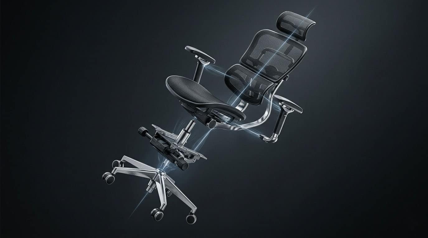
Our deep root in complete ergonomic seating manufacturing is our ultimate unfair advantage. We don’t just understand isolated parts; we understand how they govern the entire chair ecosystem. We leverage this system-level validation to redesign and upgrade your components—ensuring physical compatibility and structural superiority.
Customization Across the Entire Seating Architecture.
Unlike general traders, we execute precision tooling and custom modifications across all critical seating modules:
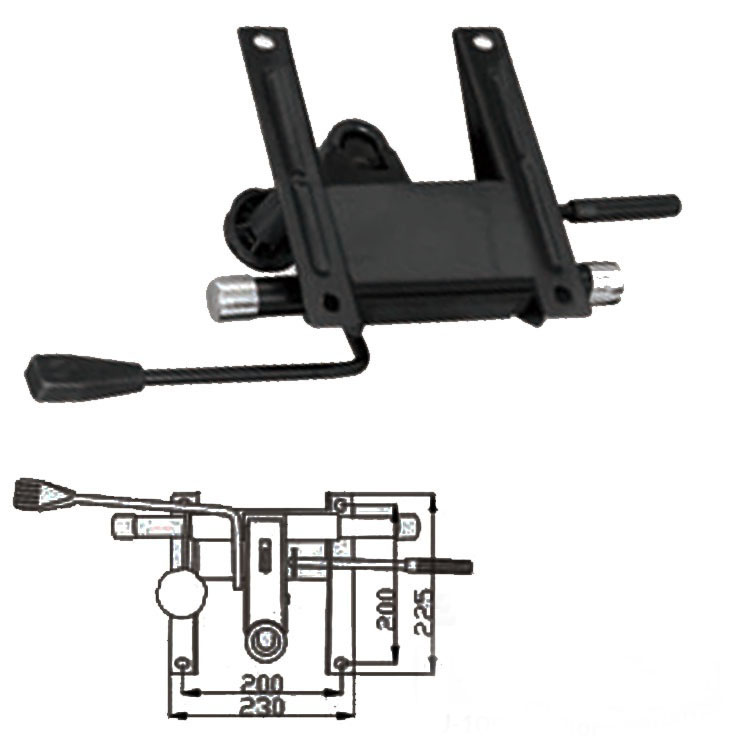
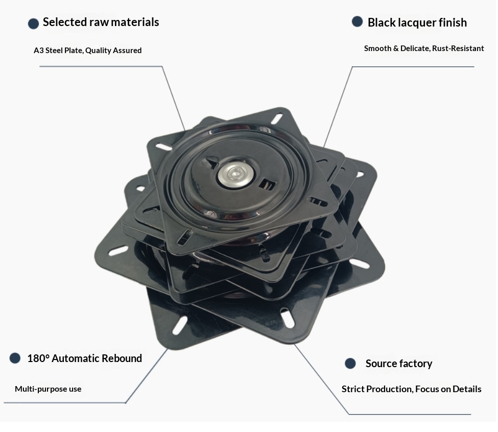
Mechanisms: Heavy-duty tilt retrofits & discontinued lock systems.
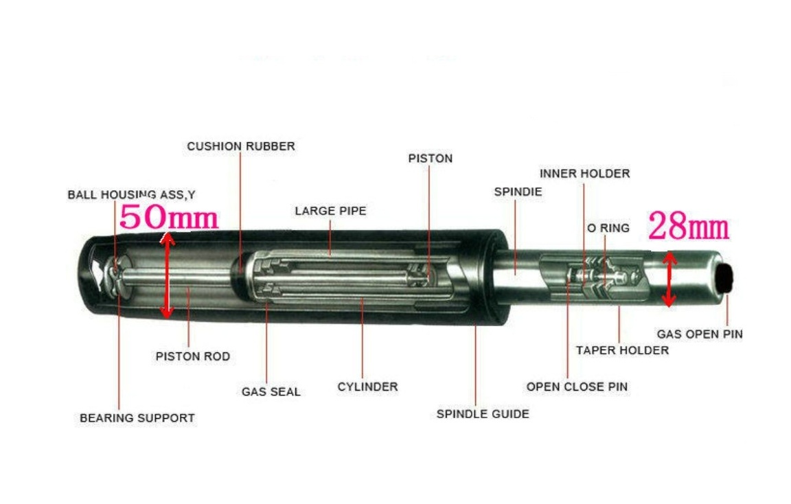
Gas Lifts: Custom dimensions, specialized stroke lengths (Class 4).
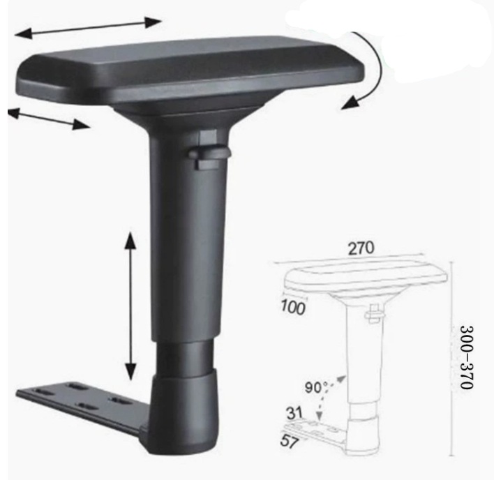
Armrests: Bespoke 3D/4D brackets & reinforced structural frames.
Bases: High-load aluminum/nylon redesigns.
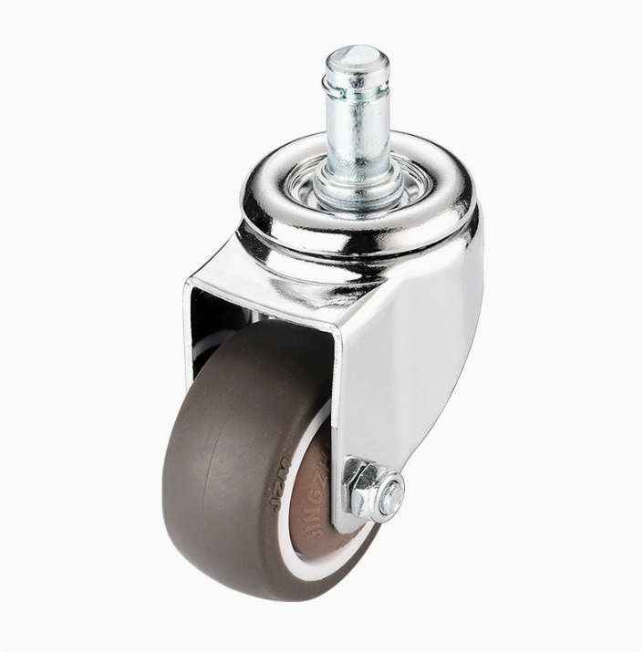
Casters: Medical-grade, anti-static, or custom noise-reduction mobility.
Original Factory Vanished? Molds Destroyed?
Your high-value ergonomic chairs shouldn’t be scrapped because of one obsolete plastic lever. We specialize in discontinued chair parts replacement. We don’t force you into “close-enough” approximations. We deliver 1:1 engineered replacements that fit your existing assets flawlessly.
The Execution Matrix
How a difficult component moves from uncertainty to a validated, repeatable manufacturing solution.
Protocol 1.01: Geometry, Motion & Load Review
A CAD model defines geometry, but not how the completed assembly behaves under motion and load. We review critical interfaces, movement paths, clearances, and load-bearing features before production. Where required, kinematic or load analysis can be used to identify interference points and structural bottlenecks before material is committed.
Protocol 1.02: Prototype Before Tooling
Moving directly from CAD to production tooling can lock a project into an unverified design. For custom components, we use 3D SLA printing, CNC rapid prototyping, or other suitable methods to verify critical dimensions, fit, clearance, and function before major tooling commitments are made.
Protocol 1.03: Critical Interface Mapping
Where dimensional variation matters, we use CMM or other appropriate measurement methods to map mounting holes, pivot axes, reference surfaces, and other critical features. The goal is to distinguish nominal dimensions from real-world variation and create a reliable engineering reference for prototype and production fitment.
Protocol 1.04: Tension & Control Calibration
Spring selection affects recline resistance, return force, and control behavior. For customized mechanisms, we evaluate spring rate and operating force against the intended load range, seat geometry, tilt characteristics, and control requirements, then verify the result physically before production.
Protocol 2.01: Structural Material & Gauge Validation
Material grade, section thickness, weld design, and load path all influence structural performance. For load-bearing components, we evaluate the material specification and critical section requirements against the intended use rather than relying on thickness alone. Where required, prototype testing is used to validate the design before production release.
Protocol 2.02: Material Specification Control
Material selection is treated as part of the engineering specification, not as an afterthought. For critical components, we define the required material grade, reinforcement, surface treatment, and processing requirements before tooling. Incoming material verification can be used where the application requires tighter control.
Protocol 2.03: Fatigue & Cyclic Load Validation
Static strength does not fully describe long-term seating performance. Where durability is critical, we evaluate cyclic loading, repeated movement, and relevant failure modes through simulation and/or physical testing appropriate to the component and application. Applicable industry or customer-defined requirements are used as validation references rather than assumptions.
Protocol 2.04: Low-Volume Tooling Strategy
Not every custom component requires the tooling strategy used for high-volume commodity products. We evaluate the expected quantity, geometry, repeat demand, and tooling investment to determine whether machining, secondary tooling, modified tooling, or dedicated tooling provides the most practical path for the project.
Protocol 3.01: Whole-Assembly Validation
A component can perform correctly on its own and still create problems when integrated into the complete seating system. We therefore validate critical custom components in the relevant assembly to check mounting, movement, clearance, load transfer, and interaction with surrounding parts before production release.
Protocol 3.02: Configuration-Specific Validation
Existing SGS, BIFMA, or other test documentation may not fully represent a modified component or custom assembly. Where the configuration has materially changed, we use the appropriate physical validation methods to evaluate the actual prototype against the intended application and requirements.
Protocol 3.03: Motion, Noise & Friction Review
Small interface errors can become noticeable through noise, friction, vibration, or inconsistent return behavior. During assembly-level validation, we review movement paths, contact points, friction sources, and audible defects that could affect the final user experience.
Protocol 3.04: Nonconformance Containment & Re-Engineering
If a prototype reveals unacceptable weld quality, dimensional drift, interference, or other critical nonconformance, the issue is contained before production release. The affected geometry or tooling is reviewed and corrected before the design moves forward.
Protocol 4.01: Production Readiness
Once the design passes fit and functional validation, the engineering package can be prepared for repeatable production. Depending on quantity and future demand, the validated solution can be produced through the most appropriate manufacturing route, from small batches to larger production programs.
Protocol 4.02: Repeatability & Production Control
Scaling a validated design requires repeatable manufacturing, not simply more output. We use controlled production specifications, process requirements, inspection points, and appropriate CNC or automated methods to minimize specification drift as volume increases.
Protocol 4.03: Transit & Condensation Protection
Metal components can be exposed to condensation and humidity during ocean transport, especially when temperature changes occur inside sealed containers. Packaging and corrosion-control measures such as desiccants, protective wrapping, and suitable surface treatments can be incorporated according to the shipment and product requirements.
Protocol 4.04: Packaging & Logistics Optimization
For parts shipped in volume, packaging geometry can materially affect freight cost, container utilization, handling, and damage risk. Where relevant, we evaluate nesting, packaging density, SKD/CKD options, and protective materials during the production-planning stage rather than treating logistics as an afterthought.
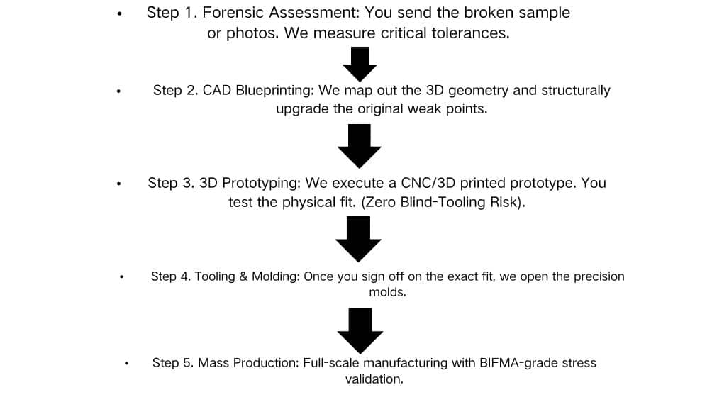
Case Study: Reverse Engineering a Discontinued Chair Mechanism
Phase 1: Physical Teardown & Diagnosis
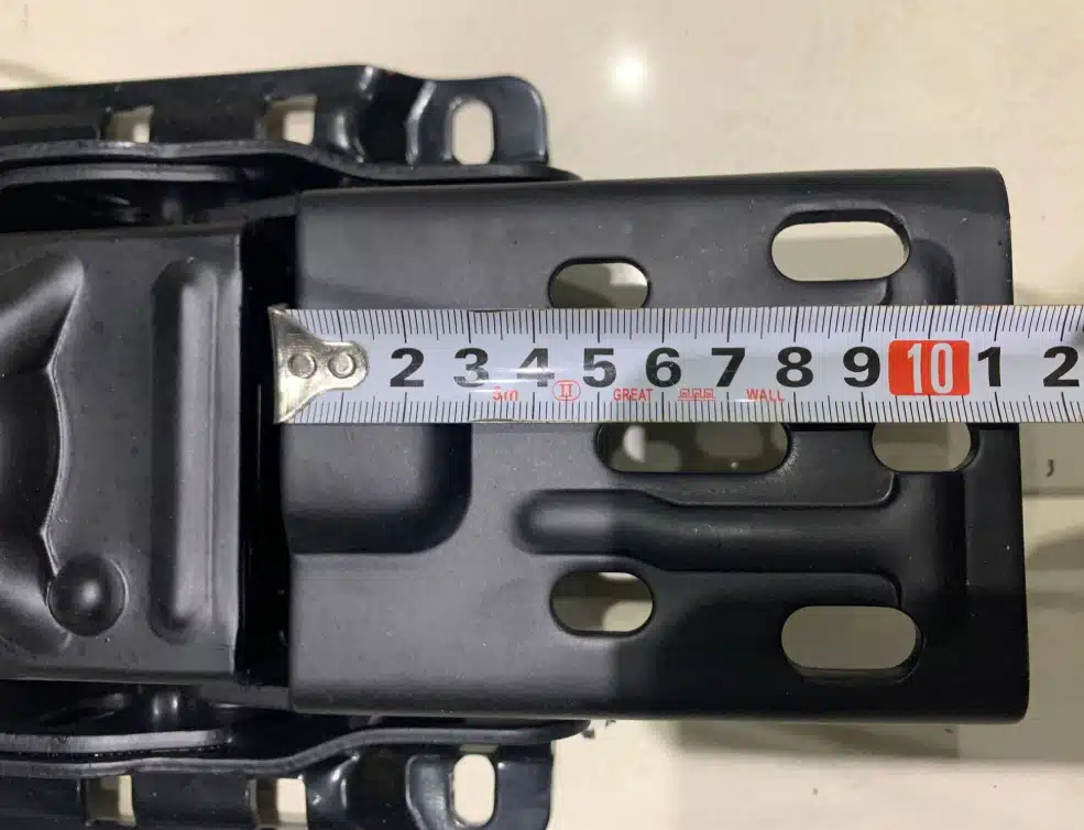
We begin with the physical component, not assumptions. The part is disassembled and inspected to identify its structure, interfaces, wear points, and critical mounting features. Key dimensions are measured against the mating assembly to establish a reliable reference for reconstruction.

Phase 2: CAD Reconstruction & Interface Mapping
Measured geometry is rebuilt into a 3D CAD model, with critical features such as mounting holes, pivot locations, clearances, and functional angles mapped against the original assembly. The model becomes the engineering reference for prototype development and fit validation before production tooling is committed.
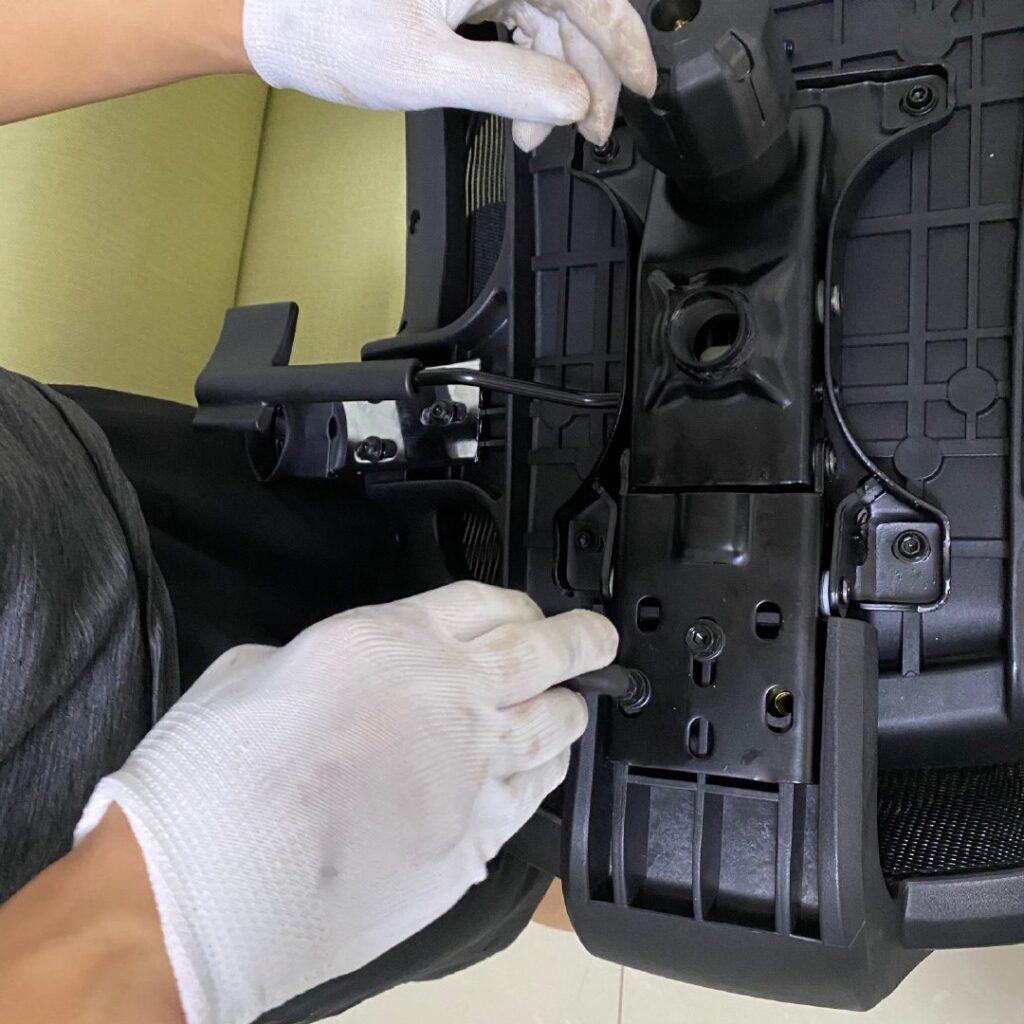
Phase 3: Prototype Fit & Interface Validation
The reconstructed mechanism is then produced as a physical prototype and checked against the target seating assembly. Critical mounting dimensions, hole positions, clearances, and interface relationships are verified on the actual assembly before the design moves into production.
Q1: We only have a broken component from a discontinued chair. Can you reproduce it?
A: Yes. Send us the broken sample or detailed 3D scans. Our reverse-engineering team will reconstruct the CAD blueprint, reinforce weak points, and produce exact-fit replacements. We specialize in hard-to-find obsolete seating parts.
Q2: How do you guarantee the custom mechanism will fit our existing chair frames before mass production?
A: We eliminate “blind tooling.” Before opening any steel molds, we CNC or 3D-print a physical 1:1 resin prototype and air-freight it to you for physical test-fitting. Molds are only cut after you approve the physical fit.
Q3: What is the Minimum Order Quantity (MOQ) for custom tooling parts?
A: Developing the prototype has NO traditional MOQ (we make ONE for you to test). Once the tooling is completed and verified, our mass production MOQ is highly flexible depending on the part’s material. Contact us with your specific volume needs.
Q4: Will you refund the mold/tooling cost?
A: Yes. We view tooling as a shared investment. The tooling fee is fully refunded once your cumulative order quantity reaches the agreed threshold for that specific part.
Q5: Will my custom design be sold to your other clients?
A: Absolutely not. For any custom-engineered or branded parts, we sign a strict Non-Disclosure Agreement (NDA). The molds you pay for belong to your intellectual property portfolio.
The Anti-Blackbox Engineering Protocol.