A Practical Framework for Maximum Compatibility, Minimum Cost, and Reliable Refurbishment
When refurbishing office chairs, compatibility is often harder than it first appears.
- A replacement mechanism may be available.
- The chair may still be structurally sound.
- The upholstery may still be usable.
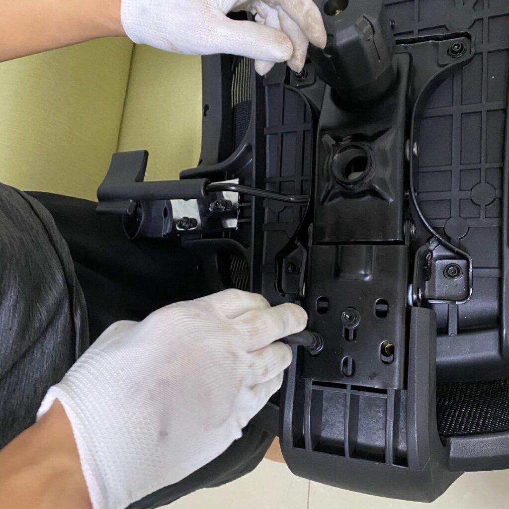
Yet the mounting pattern does not match.
A few millimeters can be enough to prevent assembly.
The immediate reaction is often:
“We need an adapter plate.”
That sounds simple.
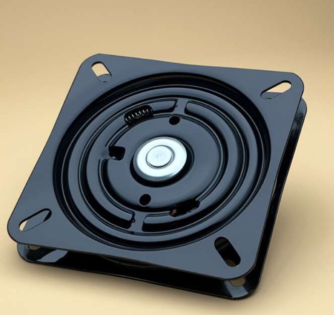
But designing an adapter that can support multiple chair models is not simply a matter of adding more holes.
Different chairs can have different:
- hole spacing
- hole count
- hole diameters
- mounting references
- seat geometry
- mechanism dimensions
- bolt sizes
- load requirements
- vertical offsets
- clearance requirements
And when multiple variables are combined, the real engineering problem becomes much larger.
The objective should therefore not be:
How can we make one adapter fit everything?
A better objective is:
How can we build the smallest, most reliable, and most economical adapter architecture that covers the largest practical share of real refurbishment demand?
That is the difference between making a part and designing a solution.

1. Why Does This Compatibility Problem Exist?
The adapter problem usually appears because two different generations of products were never designed to work together.
For example:
Original chair
↓
original mounting pattern
Replacement mechanism
↓
different mounting pattern
Neither product is necessarily defective.
They were simply designed around different interfaces.
The problem becomes more common when:
- the chair model is old
- the original mechanism is discontinued
- the original manufacturer no longer supports the model
- the refurbishment company wants to use a newer replacement mechanism
- several chair models need to be serviced using a smaller number of replacement components
The visible problem is a mismatch.
The underlying problem is:
A compatibility gap between existing assets and available replacement components.
2. Why One “Universal” Adapter Plate Is Not Automatically the Best Solution
The word universal is attractive because it appears to promise one SKU, one production process, and one inventory item.
But engineering does not become simpler merely because more patterns are placed on the same plate.
Imagine that a single plate must accommodate:
- Pattern A
- Pattern B
- Pattern C
- Pattern D
- Pattern E
A basic approach is to put all of the holes onto one plate.
This may solve the first problem.
It may also create several others.
As the number of patterns increases:
- material between holes decreases
- edge distances may become insufficient
- stress concentrations can increase
- unused holes increase
- the plate may become larger or thicker than necessary
- installation becomes less intuitive
- production cost rises
- the plate may become unsuitable for some combinations
Therefore:
Maximum compatibility is not the same as maximum engineering efficiency.
A good adapter strategy is not the one with the most holes.
It is the one that provides the best balance between coverage, reliability, manufacturing cost, and operational simplicity.
3. Start With the Compatibility Map, Not the CAD Drawing
One of the most common mistakes is starting the drawing before understanding the population of chair models that actually needs to be supported.
The first step should be a compatibility map.
For each chair or mechanism, record:
- manufacturer
- model
- production period, when known
- seat mounting pattern
- mechanism mounting pattern
- hole count
- hole diameter
- X/Y spacing
- reference points
- mounting surface geometry
- bolt size
- expected loading
- known restrictions
Then group similar patterns.
For example:
| Pattern Group | Hole Pattern | Application | Potential Adapter |
| A | Pattern 1 | Model family 1 | Type A |
| B | Pattern 2 | Model family 2 | Type A |
| C | Pattern 3 | Model family 3 | Type B |
| D | Pattern 4 | Model family 4 | Type B |
The purpose is not to create an enormous catalog.
The purpose is to discover:
Which patterns are genuinely different, and which can be served by the same adapter architecture?
4. Micro-Case: Why Compatibility Coverage Must Be Designed, Not Guessed
Illustrative Micro-Case
Consider a refurbishment program involving 1,200 discontinued office chairs across several related models.
An initial review identifies multiple mounting patterns, including differences of approximately 15 mm in one axis.
A simple response would be to create a separate custom plate for every model.
That could mean:
1,200 chairs → multiple one-off solutions → multiple drawings → multiple manufacturing setups → higher installation complexity.
A different approach is to cluster the mounting patterns and determine which ones can safely share an adapter architecture.
For example:
12 observed patterns
↓
4 engineering families
↓
2 primary adapter platforms + controlled exceptions
The important point is not the exact numbers.
The important point is the decision method:
Do not automatically customize every chair. First determine whether multiple chair models can be absorbed into a smaller number of validated adapter families.
That can reduce:
- SKU complexity
- engineering repetition
- inventory requirements
- production setup time
- installation decisions
If this approach is used on a real project, the actual savings should be measured in:
- engineering hours
- unit cost
- installation time
- inventory value
- failed installations
- future reuse
That is the evidence that turns a design idea into a business case.
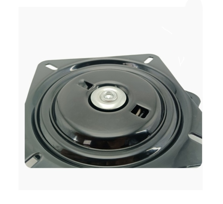
5. Standardize the Interface, Not Every Chair
This is often the key design principle.
Trying to standardize every chair is difficult.
Instead:
Standardize the replacement-side interface.
Suppose a refurbishment company normally uses only two or three replacement mechanisms.
Those mechanisms can become the fixed reference.
The chair side becomes the variable interface.
This transforms:
dozens of individual chair models
into:
a manageable number of interface families.
That is much more scalable.
6. The Z-Axis Problem: Hole Spacing Is Not the Whole Story
A common mistake is to treat compatibility as a two-dimensional X/Y problem.
It is not.
A plate can have perfect hole alignment and still fail during installation because the Z-axis geometry is wrong.
This includes:
- vertical offset
- mechanism height
- seat pan clearance
- screw head clearance
- gas-lift clearance
- lever interference
- tilt-mechanism travel
- underside structure
- surrounding frame interference
For example:
An adapter may correctly align four mounting holes.
But if the adapter raises the mechanism by 8–10 mm, the resulting chair height may become unacceptable.
Or the adapter may place the mechanism close enough to the seat structure that:
- a lever cannot move
- a moving mechanism contacts the plate
- a bolt head interferes with another component
- the seat cannot return to its intended position
Therefore:
A compatible adapter must be checked in three dimensions, not just by hole coordinates.
The engineering definition of compatibility should include:
X/Y alignment + Z-axis clearance +functional movement + structural integrity
7. Structural Analysis Must Come Before Hole Expansion
An adapter plate is not just a drilling template.
It is part of the load path.
It transfers forces between:
- the seat structure
- the mechanism
- the fasteners
- the adapter
- the chair base
Therefore, adding holes without evaluating the remaining material can create a mechanically weak solution.
The design should consider:
- load path
- material thickness
- hole edge distance
- local stress concentration
- bending
- plate deformation
- bolt engagement
- fatigue
- connection stability
The objective is not simply:
“Can the bolt pass through?”
It is:
“Can the complete assembly reliably carry its intended loads throughout its expected service life?”
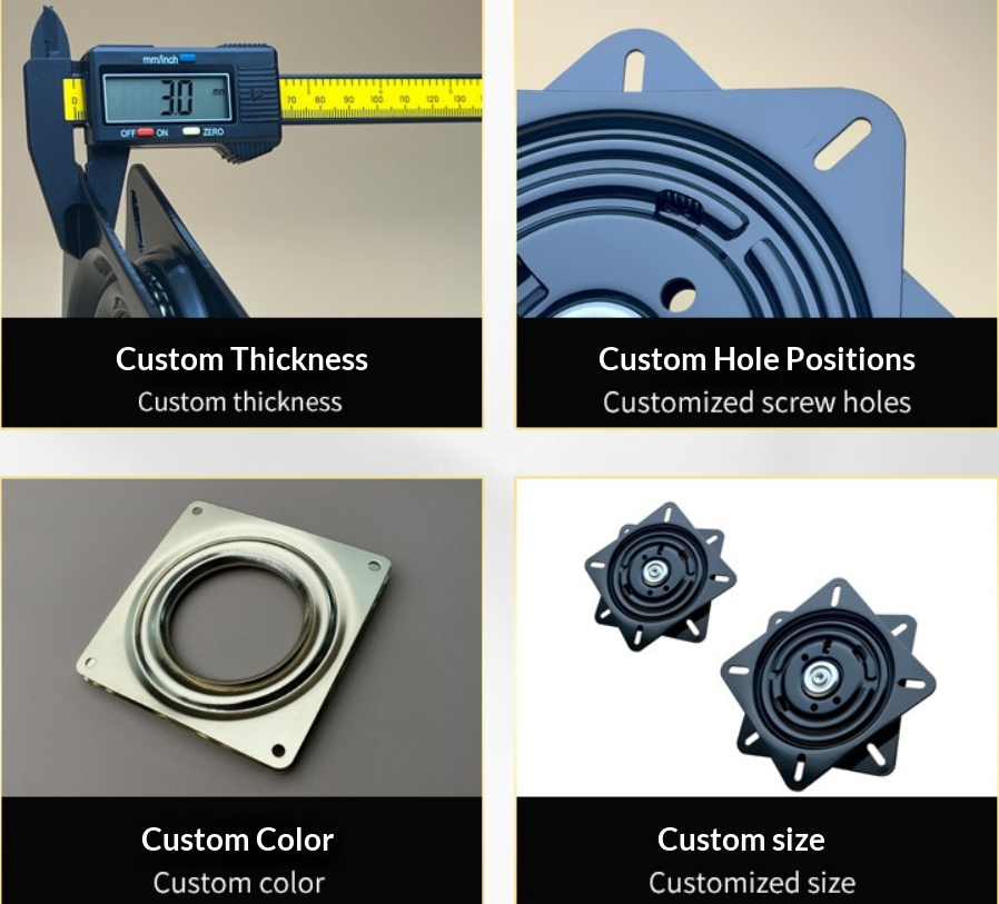
8. Three Main Adapter Strategies
There is no universal best architecture.
The right choice depends on volume, model diversity, future demand, and risk.
Strategy A — One Universal Plate
One plate contains multiple mounting patterns.
- Advantages:
- one primary SKU
- simple inventory
- potentially useful for low-volume mixed demand
- Limitations:
- more holes
- more complex geometry
- greater risk of interference
- potentially higher material cost
- potentially weaker local areas
- difficult installation in some configurations
- Best suited for: Small or irregular demand where inventory simplicity is more important than optimization.
Strategy B — A Family of Adapter Plates
Instead of forcing every pattern into one plate, create a small number of validated adapter families.
- Type A: covers a group of common patterns.
- Type B: covers another family.
- Type C: handles a less common configuration.
This approach often produces a better balance between:
- coverage
- engineering control
- cost
- inventory
The objective becomes:
Maximum practical compatibility with a limited number of SKUs.
Strategy C — A Modular Adapter System
A more advanced approach is to separate the common and variable interfaces.
- Example 1: common adapter body + interchangeable mounting module.
- Example 2: common central interface + model-specific mounting component.
This can reduce:
- tooling duplication
- inventory complexity
- development time
It can also improve:
- flexibility
- future adaptation
- repeatability
But modularity has costs. Additional interfaces can introduce:
- more assembly steps
- more fasteners
- more possible failure points
- more tolerance stack-up
Therefore:
Modular does not automatically mean better. It is better only when the reduction in development and inventory cost outweighs the additional mechanical complexity.
9. The Most Important Decision: How Much Compatibility Is Actually Worth Paying For?
This is where engineering becomes a business decision.
Suppose a database contains 100 chair models.
Maybe:
- 20 models represent 50% of actual demand;
- 35 models represent 80%;
- 60 models represent 95%;
- all 100 represent 100%.
Does reaching 100% coverage make economic sense?
Not necessarily.
A possible comparison could be:
| Solution | Coverage | SKU Count | Development Cost | Inventory Complexity |
| 3 adapter types | 80% | Low | Low | Low |
| 6 adapter types | 95% | Medium | Medium | Medium |
| 15 adapter types | 100% | High | High | High |
The optimal answer depends on the customer’s actual business.
If 5% of models create disproportionate development costs, it may be more economical to treat those as controlled exceptions instead of forcing them into the standard system.
Therefore:
The goal is not 100% theoretical compatibility. The goal is the best commercial compatibility.
10. How to Choose the Lowest-Cost Solution for a New Chair Model
When a new model appears, there are usually several choices.
- Option A: Create a completely new adapter. (Best flexibility, highest development cost.)
- Option B: Modify an existing adapter family. (Lower engineering cost.)
- Option C: Absorb the model into an existing modular interface. (Potentially lower long-term cost.)
The decision should consider:
- quantity now
- expected future quantity
- similarity to existing patterns
- development time
- tooling requirements
- unit cost
- future reuse
The first question should always be:
Can this new model be absorbed into an existing architecture?
Only if the answer is no should a new architecture be created.
That principle protects the system from uncontrolled SKU growth.
11. Prevention Starts Before Production
A mature refurbishment operation should not discover compatibility problems after purchasing hundreds of chairs.
A practical prevention process can include:
- Before purchasing, confirm:
- chair model
- mechanism model
- mounting pattern
- dimensions
- reference points
- known clearance constraints
- Before engineering, collect:
- photographs
- original components, when available
- critical measurements
- intended replacement mechanism
- Before mass production, complete:
- CAD review
- prototype installation
- functional movement check
- structural review
- fit validation
Only after validation should the solution move to larger-volume production.

12. Build the Compatibility Database Once — Reuse It Many Times
Every solved adapter problem should create reusable information.
Record:
- model
- mounting pattern
- adapter type
- dimensions
- materials
- hardware
- clearance information
- installation notes
- test results
- known failure modes
The first project may require substantial engineering effort.
The second related project should require less.
The tenth should require much less.
That is how a one-off custom project gradually becomes a repeatable system.
The true long-term asset is not the metal plate.
It is the engineering knowledge accumulated around the plate.
13. How to Measure the Real Business Value
The adapter should be evaluated using more than unit price.
A practical model is:
Total Cost of Compatibility = Development Cost + Tooling Cost + Unit Manufacturing Cost + Inventory Cost + Installation Cost + Engineering Labor + Failure / Rework Risk + After-Sales Cost + Future Modification Cost
At the same time, measure the benefits:
- More Compatible Models
- Shorter Refurbishment Time
- Lower Inventory Complexity
- Fewer Failed Installations
- Faster Response to New Models
- Higher Asset Recovery Rate
The best solution is the one that produces the best overall economic outcome.
Not necessarily:
- the cheapest plate
- the strongest plate
- the largest plate
- or the plate with the most hole patterns
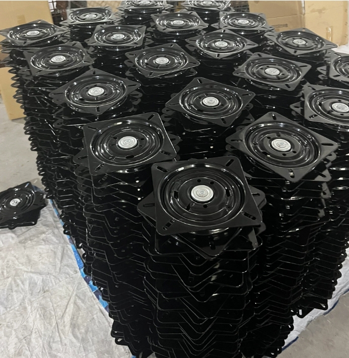
14. A Better Definition of “Universal”
The word universal should be used carefully.
A truly universal plate would attempt to fit everything.
A commercially intelligent universal system does something different:
It covers the majority of economically important patterns with a small number of validated configurations, while keeping unusual cases manageable.
That is much more realistic.
And usually much more profitable.
15. The Optimal Solution
After considering:
- compatibility coverage
- structural requirements
- Z-axis clearance
- production cost
- inventory
- installation
- future demand
- failure risk
the optimal architecture for many refurbishment environments is likely to be:
A small family of standardized adapter platforms + a compatibility database + prototype validation + controlled exceptions for unusual models.
In simple terms:
Standardize what repeats.
Customize what is genuinely unique.
This gives the refurbishment company:
- fewer SKUs
- lower development cost
- faster response
- lower inventory
- repeatable production
- better compatibility
- controlled engineering risk
16. Who Benefits From This Approach?
The solution can work at different operational scales.
- A company handling 50 local chair repairs may need a simple adapter solution and a small compatibility record.
- A company processing 500–1,000 chairs from a corporate relocation may benefit from standardized adapter families and reusable engineering data.
- A company handling 5,000+ chairs across multiple brands and models may justify a formal compatibility database, modular architecture, dedicated testing, and a controlled product family.
The principle does not change.
Only the level of investment changes.
The right solution should scale with the problem instead of forcing every customer into the same engineering model.
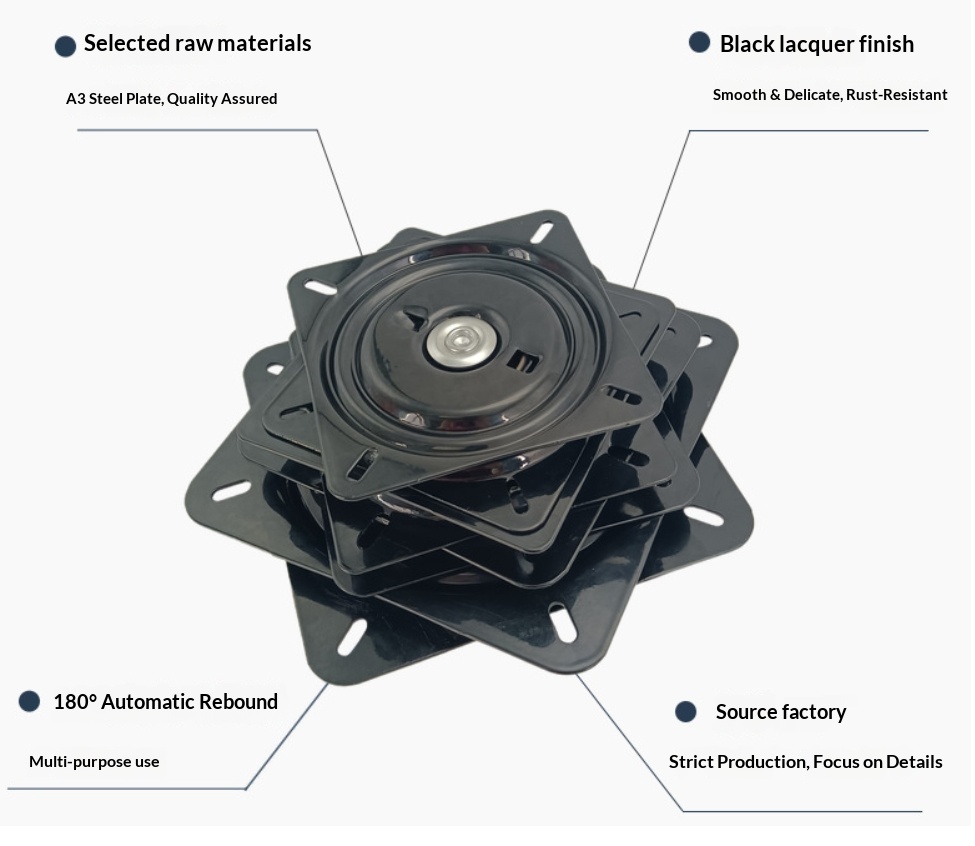
Conclusion
The real problem is not:
“How can we make one adapter plate fit every office chair?”
That question can lead to an unnecessarily complicated product.
The better question is:
“How can we build the smallest, most reliable, and most economical adapter system that covers the majority of real refurbishment demand?”
That changes the goal from universal compatibility to optimal compatibility.
And that is where the real value lies.
- The product is the adapter plate.
- The engineering is the compatibility architecture.
- The business value is the reduction in development cost, inventory, installation time, failure risk, and lost asset value.
A good adapter solves a mounting problem.
A good adapter system solves a recurring business problem.
The goal is not to make one plate fit everything.
The goal is to make the right solution repeatable, economical, and reliable.